

ERW Solutions: In-Line ERW Tube Inspection System
Product Description
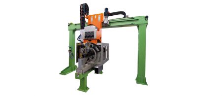
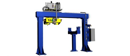
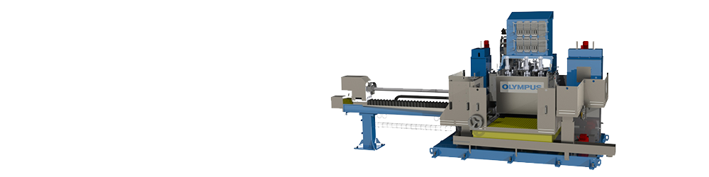
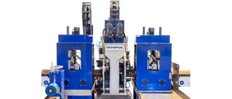
The in-line electrical resistance weld (ERW) tube inspection system is a turnkey solution that uses phased array technology integrated into a fully automated testing system to meet stringent inspection requirements. Key benefits include:
- Automatically tracks the heat-affected zone (HAZ)
- Visualize the profile of welds in real time
- Minimize your dependency on operator skill with automatic calibration
- Detect defects at production speed with calibration check
- Reduce the risk of equipment damage with a pipe window detector
Designed to be an easy-to-use solution for helping ensure the quality of ERW tubes post welding, annealing, and sizing, the system includes:
- Dedicated project management
- Instruments, probes, and mechanical equipment
- Water management system
- Software
- Commissioning, training, and after-sales support
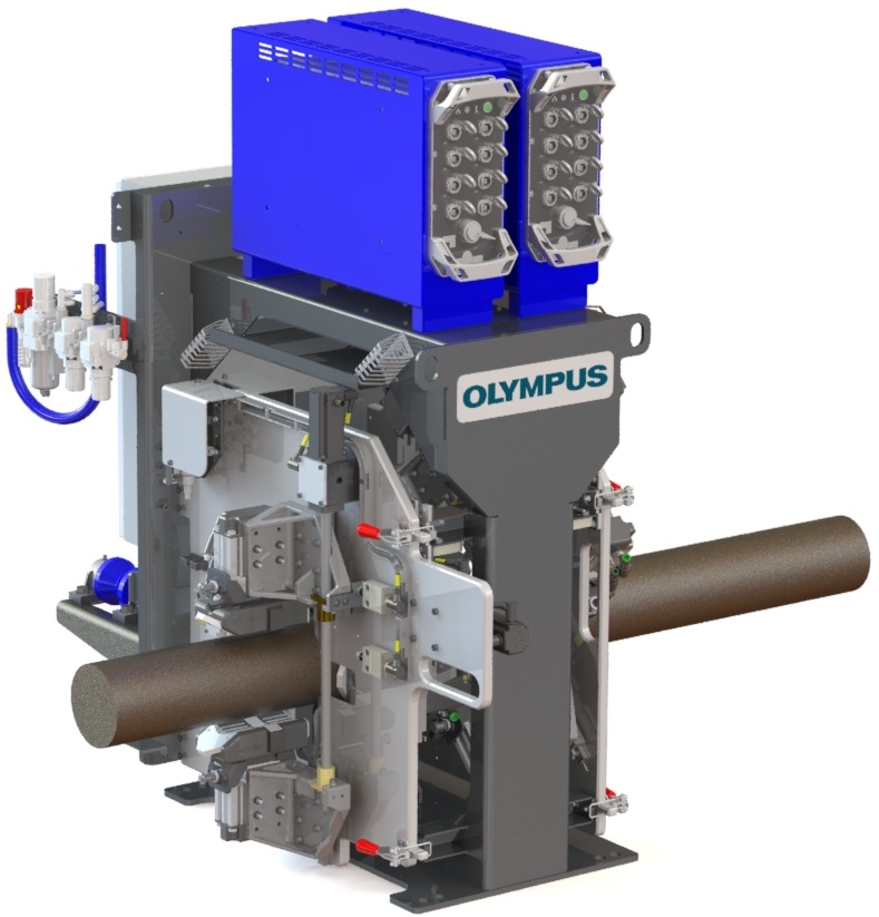
Profile and Track Welds while Detecting Flaws
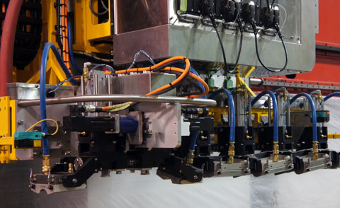
A cylindrical phased array (PA) probe is located on each side of the tube’s weld to inspect in both clockwise and counterclockwise directions. To track welds and create a weld profile, a cylindrical PA probe located on the weld fires at zero degrees. Scarfing is automatically monitored, and the weld is profiled to create a side view for fast analysis.
- Wide coverage of the heat-affected zone (HAZ)
- Continuously monitor the weld profile and HAZ to perform analysis without waiting for the pipe to be cut
- Constant amplitude detection within the entire inspection area, even with mechanical movement
- Novel water wedge enables many degrees of freedom to accommodate pipe movement and provide excellent coupling
Automatic Weld Tracking
Our unique algorithm, based on time-of-flight analysis, automatically detects the scarfing area and sends feedback to the PLC to automatically adjust the inspection for each water wedge.
Fast Inspections, High-Quality Results
Our high-speed inspection systems are designed to meet the productivity requirements of the metal manufacturing industry. The systems adhere to the highest international quality standards, without compromising quality.
- Fire more than one acoustic configuration within the same PA probe—pitch-catch or high-angle pulse echo modes can be programmed to perform mid-wall inspection
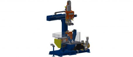
- Small, automated gantry positions the inspection head in-line or off-line for inspections, automatic calibrations, or maintenance
- Available calibration bench to perform automatic calibration and calibration check sequences at standard inspection speed
Automatic Calibration
To achieve a thorough inspection, each PA probe must be calibrated. During calibration, the apertures of each probe pass over a known defect, and the probe’s gain level is automatically adjusted. This feature enables users to easily perform and validate a precise calibration of each focal law, saving time without relying on the user’s skill.
- Calibration check performed under normal production conditions
- Each reference defect is validated to help ensure they’re detected above the alarm level
- Results are displayed in easy-to-interpret views
Reviews
There are no reviews yet.